M5wificom Project Overview
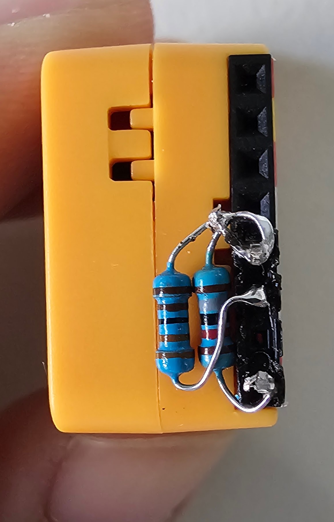
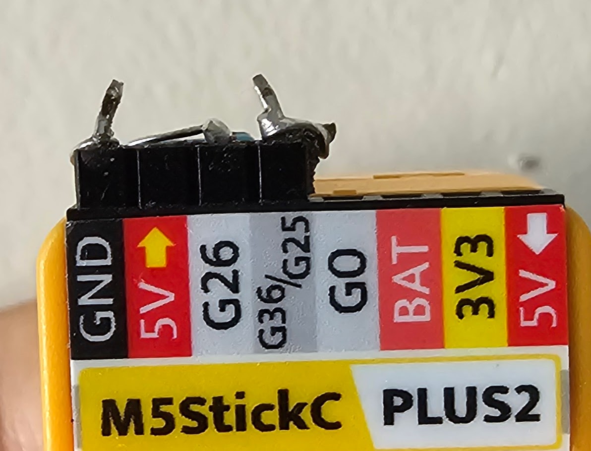
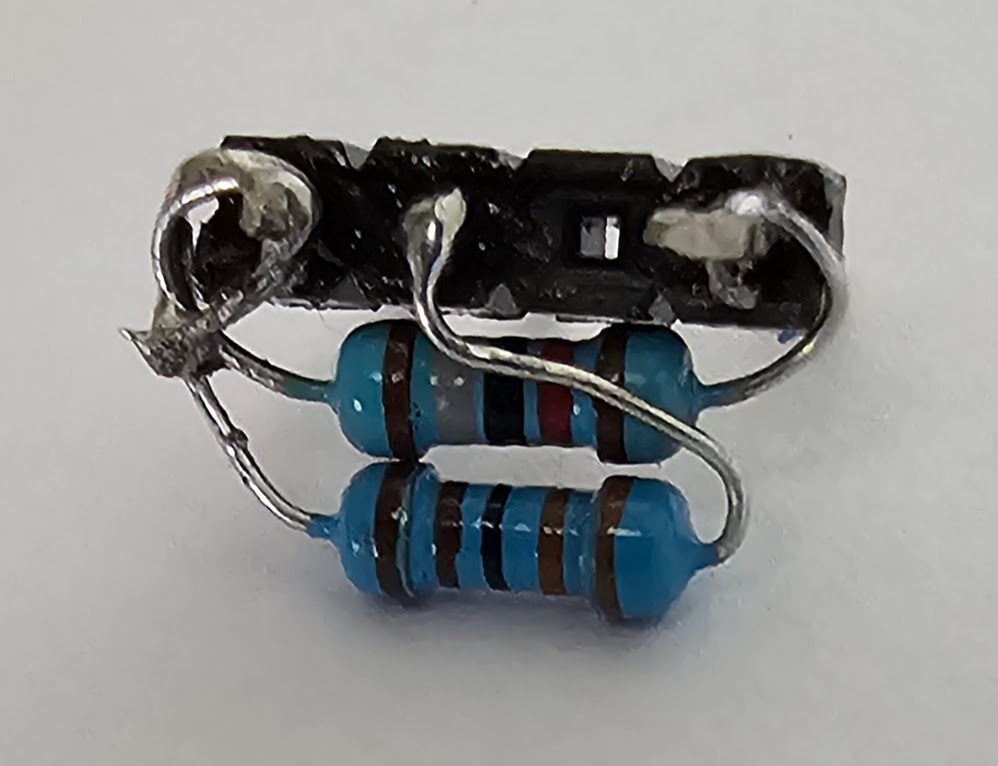
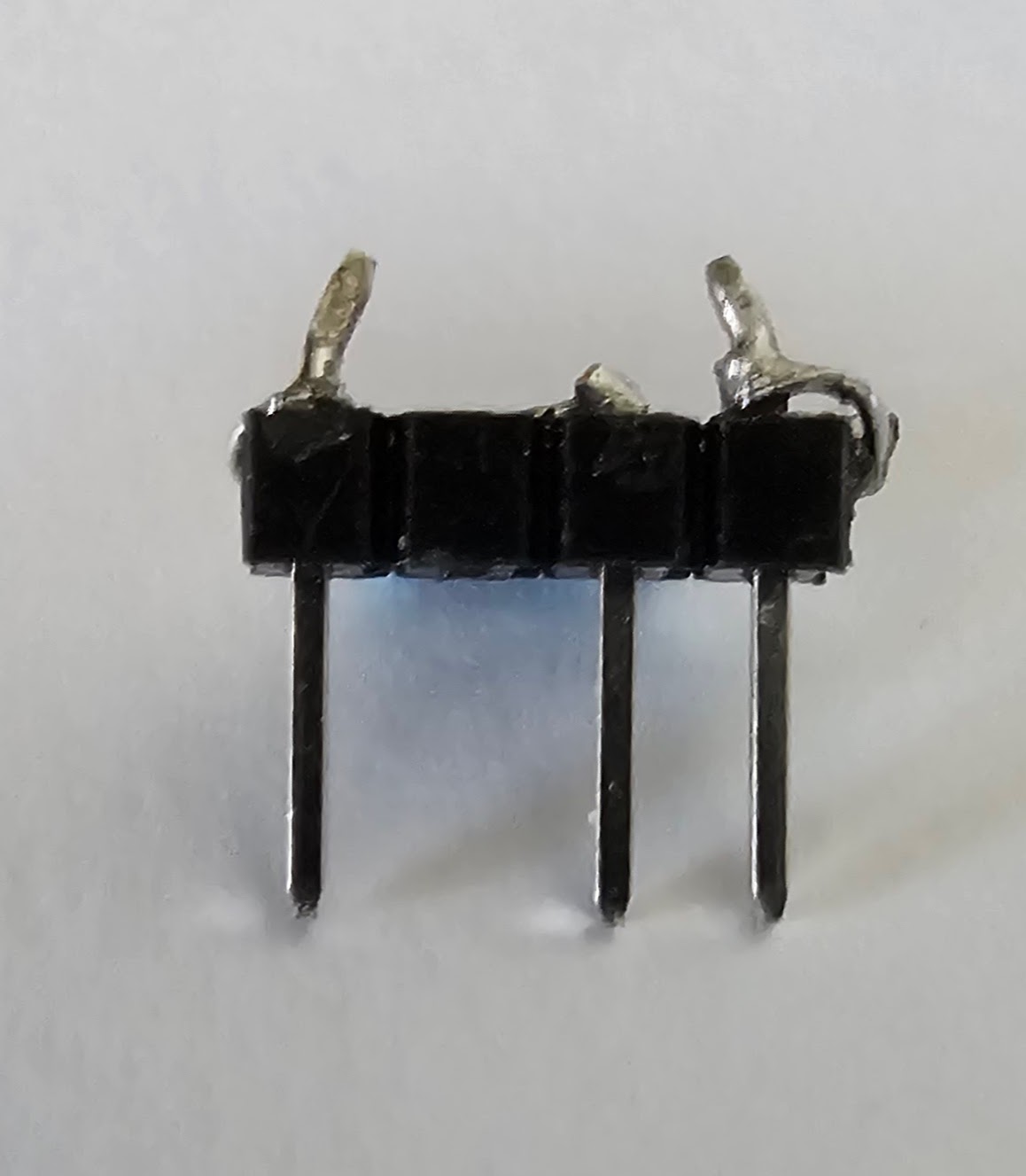
This project uses M5StickC Plus board with wificom and dmcomm libraries. The ACOM circuit uses input pin 36 and output pin 26 with 3.3K and 18K resistors. This configuration enables reliable wireless communication for your ACOM devices.
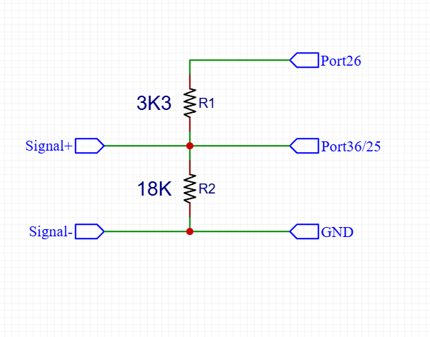
Circuit Configuration
- Input Pin: GPIO36
- Output Pin: GPIO26
- R1: 1/4w 3.3K Ω
- R2: 1/4w 18K Ω
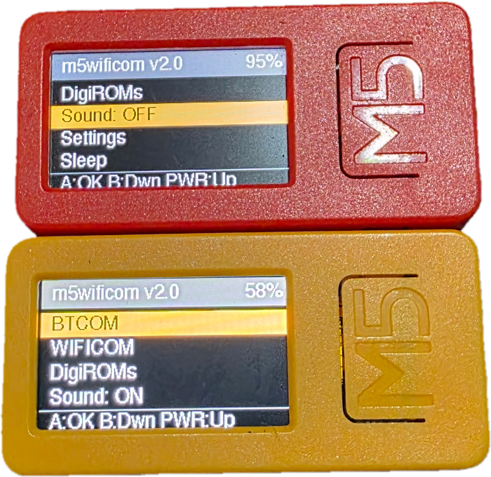
Button Controls
- Button A: Click = ENTER / Hold = RESTART
- Button B: Click = Down Menu
- Button PW: Click = Up Menu / Hold = Power
HOW TO FLASH
- 1. Connect M5StickC to your PC via USB
- 2. Open this page in Google Chrome (preferred)
- 3. Click the FLASH/CONFIG button above
- 4. Select your M5Stack COM port from the dialog
- 5. Click INSTALL button 2 times
- 6. Done! Your device is ready
HOW TO CONFIGURE
- 1. Connect M5StickC to your PC via USB
- 2. On device, go to ACOM SETTING Menu
- 3. Open this page in Google Chrome
- 4. Click the Connect button in M5WIFICOM Device Configurator
- 5. Fill in WiFi and server settings
- 6. Click Write Data to save settings

M5StickC-PLUS
Version 2.0
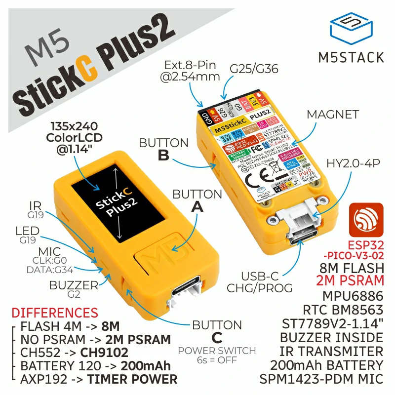
M5StickC-PLUS2
Version 2.0
Configure your M5WIFICOM device
Connect device via Web Serial API before accessing SETTING menu
WiFi Configuration
WiFi #1 (Primary)
WiFi #2 (Backup)
WiFi #3 (Backup)
WIFICOM Server Parameters
Paste Configuration
Paste your `secrets.py` or JSON configuration file content
Console Log
Waiting for connection...
Base libraries from: BrassBolt@wificom, BladeSabre@DMComm, Martin Sloup
digiroms from: humulos, jyoshiikuta
Created by [email protected] | © 2024 M5wificom Project